The Usage of Multi Functional Fiber Holder
The Usage of Multi Functional Fiber Holder
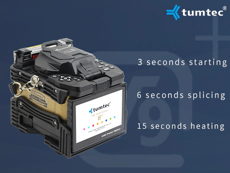
Speak with authority, quality is trustworthy.
If you're putting in single mode fiber, the most typical connector kind might be UPC . Connectors are available with differently polished endfaces, which impacts the connector’s degree of return loss . Single mode connectors can be found both as a UPC or APC (Angled Physical Contact/Angled Polish Connector).
To measure the length and attenuation of the fiber, we place the markers on both finish of the section of fiber we want to measure. The OTDR will calculate the distance distinction between the 2 markers and provides the distance.
Place one of the markers on the OTDR on the fiber segment to be examined away from any splice or connection within the cable underneath take a look at. This is your 'QuickStart' guide to testing fiber optic cable crops with an OTDR. We'll provide the primary information you need and supply some printable references. Just go to the subjects below to seek out the data you want. Links to videos and extra comprehensive info might be supplied in each section.
Multimode fibers require either a 50/one hundred twenty five µm (OM2/OM3/OM4) or 62.5/125 connector. For extra info on the distinction between single mode and multimode fibers, visit our article. Single mode makes use of a 9/one hundred twenty five connector, which refers to the core and cladding diameter of the optical fiber (i.e. core of 9 µm and cladding of a hundred twenty five µm).
It will also read the distinction between the facility levels of the 2 factors where the markers cross the trace and calculate the loss, or distinction within the two power ranges in dB. Finally, it will calculate the attenuation coefficient of the fiber by dividing loss by distance and present the end in dB/km, the traditional items for attenuation. The slope of the fiber hint shows the attenuation coefficient of the fiber and is calibrated in dB/km by the OTDR. In order to measure fiber attenuation, you need a reasonably lengthy length of fiber with no distortions on either finish from the OTDR decision or overloading due to large reflections.
Fiber connectors are designed specifically for the type of fiber you are using. ST ConnectorA ST connectors is a 2.5 mm AT&T™-designed connector.
If the fiber seems nonlinear at both finish, especially close to a reflective event like a connector, keep away from that section when measuring loss. The quantity of sunshine scattered back to the OTDR is proportional to the backscatter of the fiber, peak power of the OTDR test pulse and the size of the heart beat despatched out. If you need extra backscattered mild to get good measurements, you can improve the heartbeat peak power or pulse width or send out extra pulses and average the returned indicators. All three are used in many OTDRs, with consumer control of a few of the choices.

Hot Line:+86 020-22818328
Customer Service: 400-678-6206 / E-mail: Master@weyes.cn
Office Add: The Entire Floor Of 5af And 30f Of Xingguang Yingjing Building, No.117 Shuiyin Road, Yuexiu District, Guangzhou City, Guangdong Province
Copyright © 2021 Guangzhou Weyes Network Technology Co., Ltd. | All Rights Reserved


![[Dry Goods] how to avoid electrode rod after fusion black?](https://img5811.weyesimg.com/uploads/tumtecchina.com/images/15840915146146.jpg?imageView2/2/w/1920/q/100/format/webp)