The Usage of Multi Functional Fiber Holder
The Usage of Multi Functional Fiber Holder
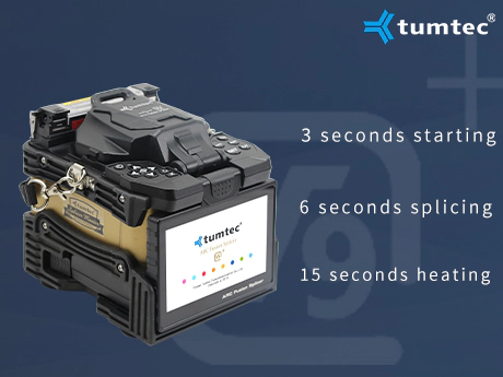
Speak with authority, quality is trustworthy.
The supply and meter duplicate the transmitter and receiver of the fiber optic transmission link, so the measurement correlates well with precise system loss. The OTDR, nevertheless, makes use of a unique optical phenomena of fiber to not directly measure loss. The Optical Time Domain Reflectometer is helpful for testing the integrity of fiber optic cables. The OTDR is also generally used to create a 'picture' of fiber optic cable when it's newly put in.
There are additionally various adapters and patch cable configurations that can be utilized to connect fiber optic-based tools. Try another cable crops for practice - try 13km singlemode at 1310nm, 4 splices and connectors only on the ends. Use the everyday part loss knowledge below the calculator or use your own estimates. Note the large distinction between the everyday values and the TIA worst case values. If you use typical area installed connectors of the adhesive/polish kind or SOCs - fusion splice on connectors, the lower/typical values are probably a good choice.
The vertical scale is optical energy at the distance from the transmitter shown in the horizontal scale. As optical sign from the transmitter travels down the fiber, the fiber attenuation and losses in connections and splice reduces the ability as shown within the inexperienced graph of the facility. Prior to designing or installing a fiber optic cabling system, a loss finances evaluation is recommended to make sure the system will work over the proposed link. That same loss price range might be used as to match take a look at outcomes after set up of the cabling to ensure that the parts had been put in accurately.
If you employ MPO or prepolished splice connectors with mechanical splices, the TIA values could also be closer. Below the drawing of the fiber optic link above is a graph of the power within the hyperlink over the size of the hyperlink.
The OTDR makes use of this 'backscattered mild' to make measurements together with mirrored light from connectors or cleaved fiber ends. Unlike sources and power meters which measure the lack of the fiber optic cable plant directly, the OTDR works not directly.
The OTDR measures the amount of light that's returned from each backscatter within the fiber and mirrored from a connector or splice. In fiber, light is scattered in all instructions, including some scattered back towards the supply as shown here.
Later, comparisons may be made between the original trace and a second hint taken if issues arise. Analyzing the OTDR trace is at all times made easier by having documentation from the unique trace that was created when the cable was put in. Patch cables can be bought with all various configurations (SC-SC, SC-LC, and so forth.). Again, the type of tools you are installing will determine your connector wants.

Hot Line:+86 020-22818328
Customer Service: 400-678-6206 / E-mail: Master@weyes.cn
Office Add: The Entire Floor Of 5af And 30f Of Xingguang Yingjing Building, No.117 Shuiyin Road, Yuexiu District, Guangzhou City, Guangdong Province
Copyright © 2021 Guangzhou Weyes Network Technology Co., Ltd. | All Rights Reserved


![[Dry Goods] how to avoid electrode rod after fusion black?](https://img5811.weyesimg.com/uploads/tumtecchina.com/images/15840915146146.jpg?imageView2/2/w/1920/q/100/format/webp)